


Stage Series Rock Lights are the perfect solution to add useful light to your vehicle with their compact size and numerous mounting solutions. The following installation guide will provide you with basic instructions on how to mount and wire the Stage Series 8-Pack Rock Light Kit on your 2022-2024 Toyota Tundra. Check out the installation video, or continue reading for step-by-step instructions below!
NOTE: This product should not be used on a 24V system. Disconnect the negative battery terminal before starting your installation.
Table of Contents
- Installation Video
- Installation Tools
- Mounting Instructions (Front)
- Mounting Instructions (Front Wheel Wells)
- Mounting Instructions (Middle)
- Mounting Instructions (Rear Wheel Wells)
- Mounting Instructions (Rear)
- Wiring Instructions
- Questions About the Installation?
- Where Can I Buy Stage Series Rock Lights?
Installation Video
Installation Tools
- Drill
- 1/4" Drill Bit
- 5/32 Allen
- 8mm Wrench
- Ratchet
- 13mm Socket
- Zip Ties (included with Stage Series Rock Lights)
Mounting Instructions (Front)
Step 1 - Identify Mounting Location

At the front of the truck, identify the location under the front bumper where you'll mount your Stage Series Rock Light.
Step 2 - Magnet Mounted (Non-Invasive Option)
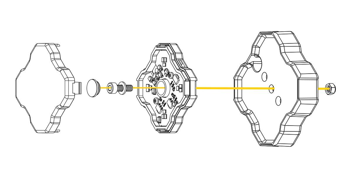
Use the included nut, bolt, and washers to mount the light as shown in the diagram above.
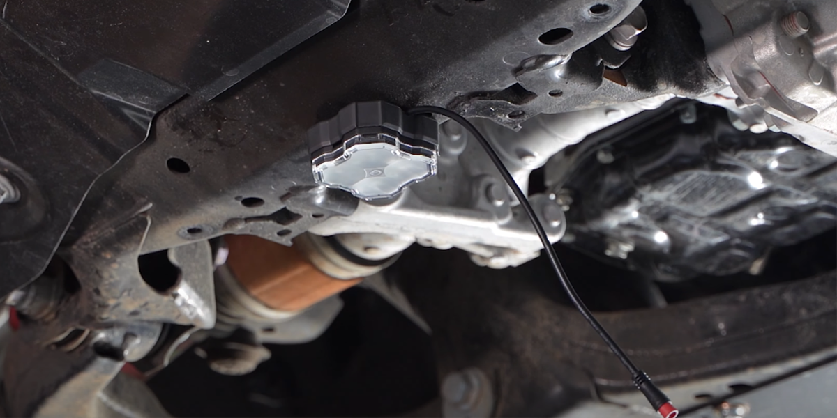
Utilizing our magnet mount with our rock light attached, place it just below the front skid plate.
Step 3 - Drill Mounting Hole (Invasive Option)

To mount the rock light using the center hole option, drill a hole using a 1/4" bit in the center of the skid plate.
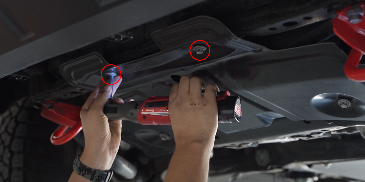
Step 4 - Remove Skid Plate

Using a 13mm socket, remove the (2) 13mm bolts from the front of the skid plate for easier access.
Step 5 - Prepare Rock Light for Mounting
Remove the outer lens from your rock light, then remove the center rubber dust seal.
Step 6 - Mount Rock Light
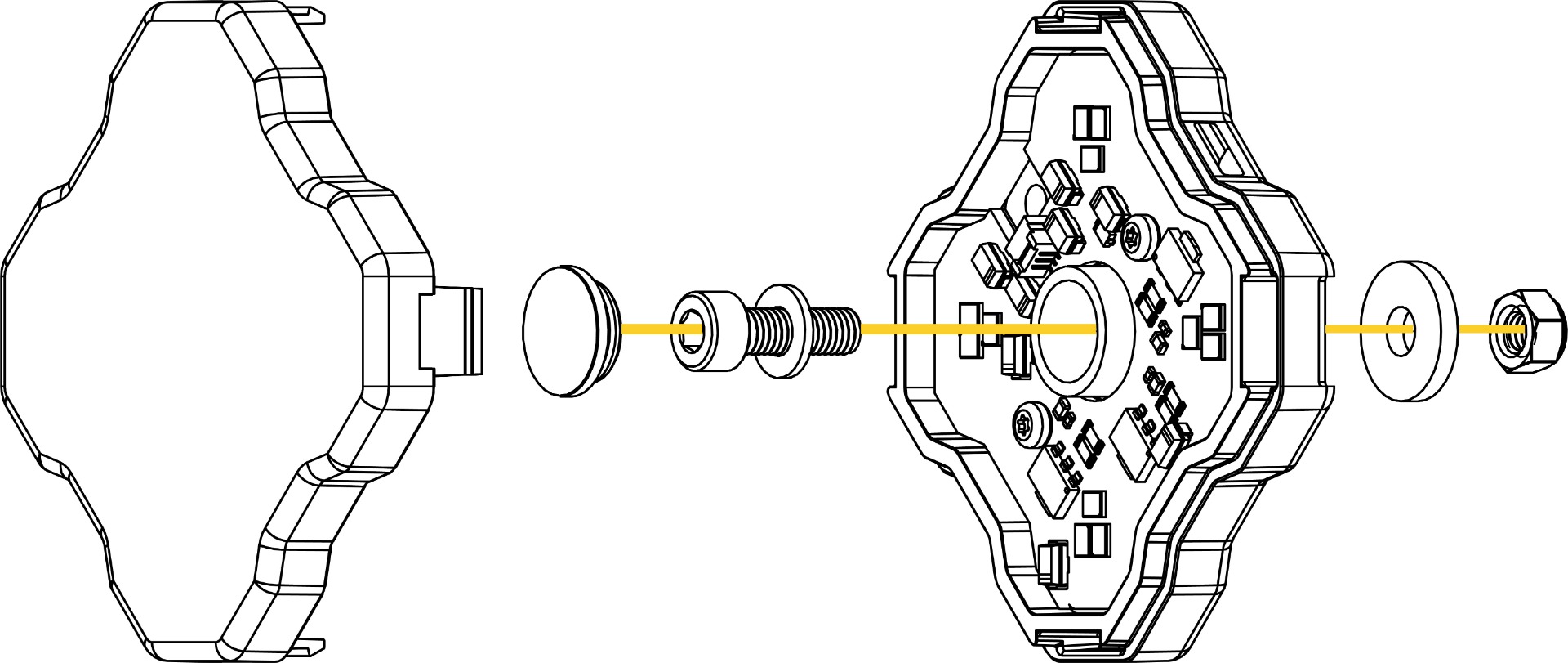
Use the included nut, bolt, and washers to mount the light as shown in the diagram below.
Step 7 - Secure Rock Light
Use a 5/32nd allen and 8mm wrench to secure our rock light to the skid plate.

Step 8 - Mount with Zip Ties (Optional)
You may alternatively use zip ties for mounting the rock light to any available attachment point, with integrated tabs on each side of the light.
Step 9 - Reassemble Rock Light
Reinstall the rubber dust seal and clip the lens into position.
Mounting Instructions (Front Wheel Wells)
Step 1 - Identify Mounting Location

At the front of the truck, identify within the left and right front wheel wells where you'll mount your Stage Series Rock Light.
Step 2 - Magnet Mounted (Non-Invasive Option)


Utilizing our magnet mount with our rock light attached, place it on the side of the frame rail right above the CV axle (Option 1) or under the body on the frame rail right below the lower control arm (Option 2).
Step 3 - Remove Fender Liner (Invasive Option)
Using a 10mm socket, remove the (1) 10mm bolt from the fender liner along with (5) plastic clips.
Step 4 - Drill Mounting Hole

To mount the rock light using the center hole option, drill a hole using a 1/4" bit in the carpet fender liner.
Step 5 - Prepare Rock Light for Mounting
Remove the outer lens from your rock light, then remove the center rubber dust seal.
Step 6 - Mount Rock Light
Use the included nut, bolt, and washers to mount the light as shown in the diagram below.
Step 7 - Secure Rock Light

Use a 5/32" Allen and 8mm wrench to secure our rock light to the carpet fender liner.
Step 8 - Mount with Zip Ties (Optional)
You may alternatively use zip ties for mounting the rock light to any available attachment point, with integrated tabs on each side of the light.
Step 9 - Reassemble Rock Light
Reinstall the rubber dust seal and snap the lens into position.
Mounting Instructions (Middle)
Step 1 - Identify Mounting Location
Along the sides of the truck, identify the underbody section on either side where you'll mount your Stage Series Rock Light.
Step 2 - Magnet Mounted (Non-Invasive Option)


Utilizing our magnet mount with our rock light attached, place it on the bottom of the cab between the frame rail and side steps (Option 1), or on the bottom of the frame rail (Option 2).
Mounting Instructions (Rear Wheel Wells)
Step 1 - Identify Mounting Location

At the front of the truck, identify within the left and right rear wheel wells where you'll mount your Stage Series Rock Light.
Step 2 - Magnet Mounted (Non-Invasive Option)

Utilizing our magnet mount with our rock light attached, place the light directly on the frame rail in front of the shock.
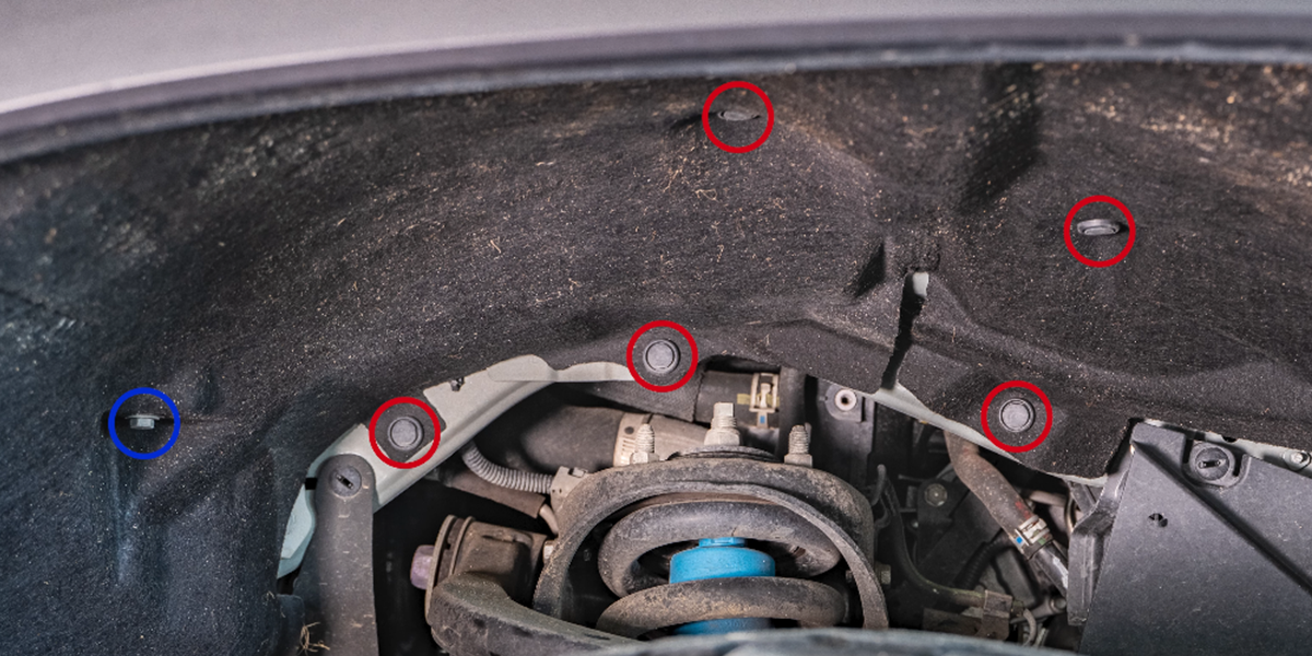
Step 3 - Remove Fender Liner Hardware (Invasive Option)

Using a plastic trim removal tool, remove the (2) plastic clips from the top of the fender liner.
Step 4 - Drill Mounting Hole

To mount the rock light using the center hole option, drill a hole using a 1/4" bit on the plastic fender liner between the two plastic clips.
Step 5 - Prepare Rock Light for Mounting
Remove the outer lens from your rock light, then remove the center rubber dust seal.
Step 6 - Mount Rock Light
Use the included nut, bolt, and washers to mount the light as shown in the diagram below.
Step 7 - Secure Rock Light
Use a 5/32" Allen and 8mm wrench to secure your rock light to the plastic fender liner.

Step 8 - Mount with Zip Ties (Optional)
You may alternatively use zip ties for mounting the rock light to any available attachment point, with integrated tabs on each side of the light.
Step 9 - Reassemble Rock Light
Reinstall the rubber dust seal and clip the lens into position.
Mounting Instructions (Rear)
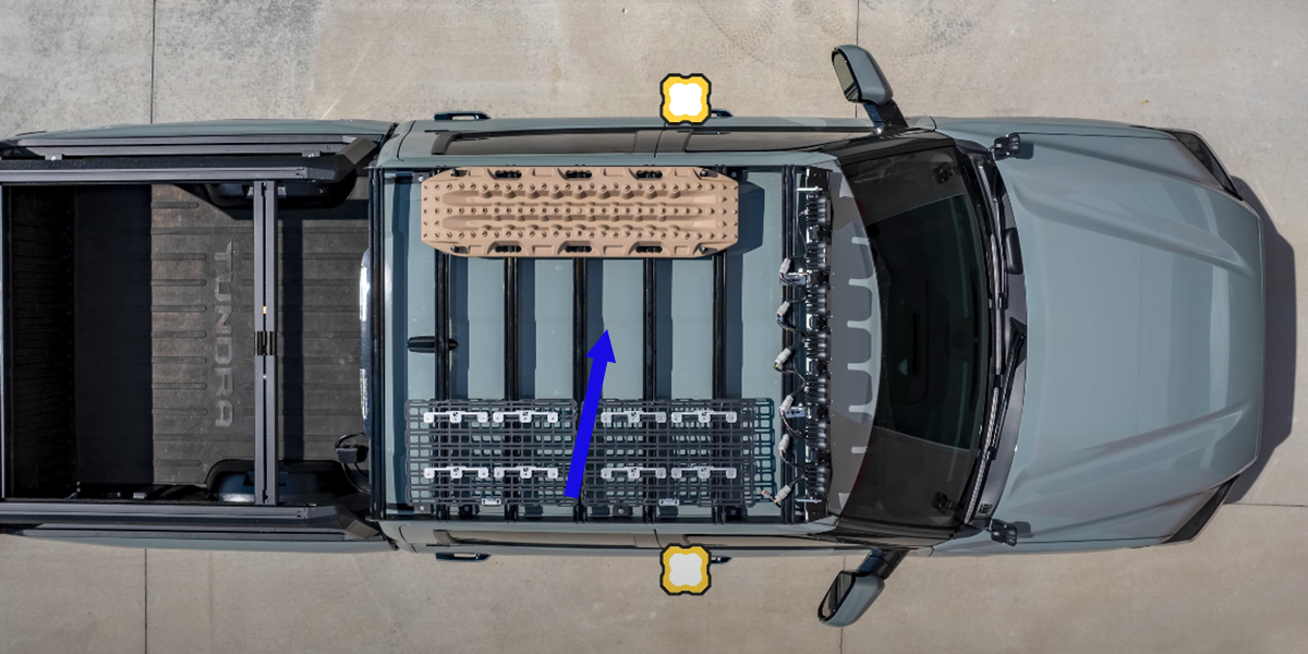
Step 1 - Identify Mounting Location

At the rear of the truck, locate the hitch where you'll mount your Stage Series Rock Light.
Step 2 - Magnet Mounted (Non-Invasive Option)

Utilizing our magnet mount with our rock light attached, place it underneath the rear hitch.
Wiring Instructions
Step 1 - Connect 3M M8 Extension Wire (Rear to Left Rear Wheel Well)
Connect a 3M M8 Extension Wire at the rear hitch Rock Light and route it over the frame and up to the left rear wheel well keeping away from any hot or moving parts.

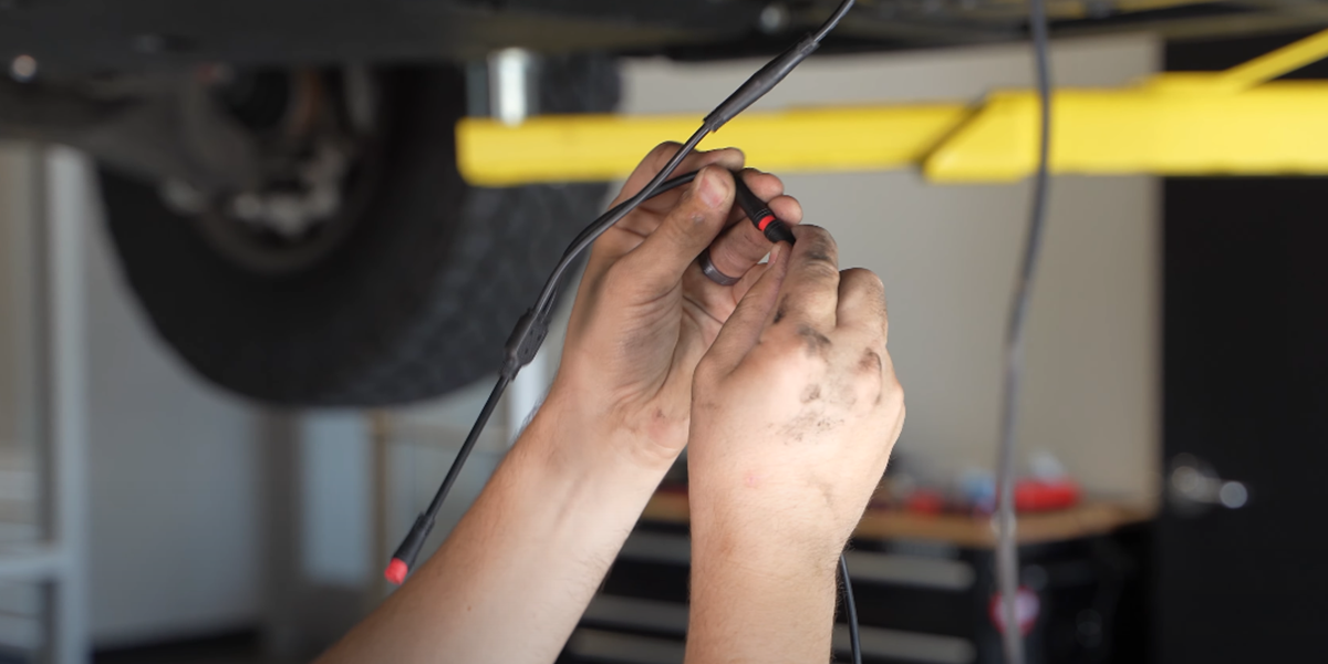
Step 2 - Connect M8 Splitter (Left Wheel Well)
Connect the M8 Splitter to the 3M Extension Wire and our rear wheel well-mounted Rock Light.

Step 3 - Connect 5M M8 Extension Wire (Left Rear Wheel Well to Middle)
Connect a 5M M8 Extension Wire to the M8 splitter before routing an excess wiring behind and over the fender liner.

Re-install your (2) plastic fender liner clips removed earlier and secure any loose wiring using zip ties.

Route the 5M M8 Extension from the rear wheel well, over the body mount, and down along the frame rail to the middle rock light.

Step 4 - Connect M8 Splitter (Left Middle)
Connect the M8 Splitter to the 5M Extension Wire and our middle Rock Light.
Step 5 - Connect 5M M8 Extention (Left Middle to Center)
Connect a 5M M8 Extension Wire to the M8 splitter then route it between the frame rail/side step along the brake lines.

It's important to secure any excess wiring up and out of the way using zip ties.

Step 6 - Connect 5M M8 Extension (Rear Right Wheel Well)
Connect a 5M M8 Extension Wire to the Rock Light and route the wiring behind and over the fender liner and down to the frame rail.

Re-insert the (2) plastic clips remove earlier.

Route the 5M M8 Extension from the rear wheel well, over the body mount, down along the frame rail, and the brake lines to the middle rock light.

Step 7 - Connect M8 Splitter (Right to Middle)
Connect the M8 Splitter to the 5M Extension Wire and our middle Rock Light and secure any excess wiring using zip ties.

Step 8 - Connect 3M M8 Extension (Middle to Right Front Wheel Well)
Connect the 3M M8 Extension to the splitter and route it along the frame rail and the brake lines to the front right wheel well.

Step 9 - 5M Extension Engine Bay Routing
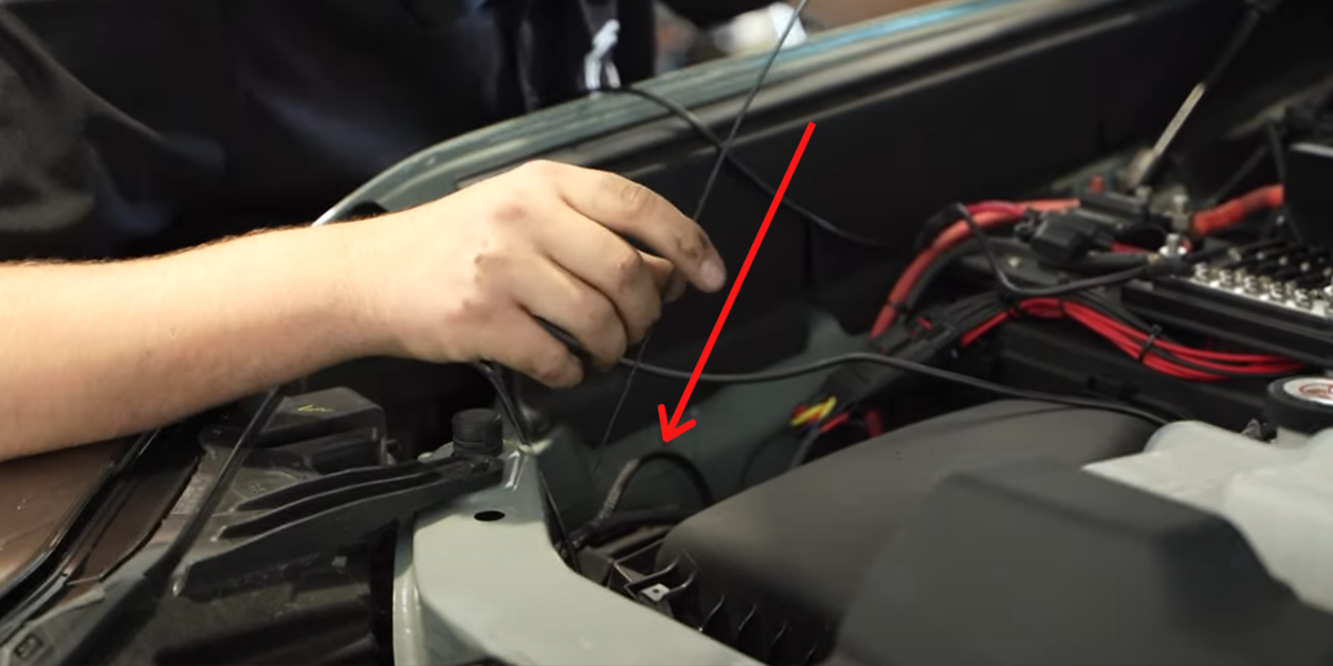
Moving back to the driver's side of the Tundra, route the 5M M8 Extension connected to your left-middle Rock Light up into the engine bay.

Use steel fish tape and feed it down through the engine bay.

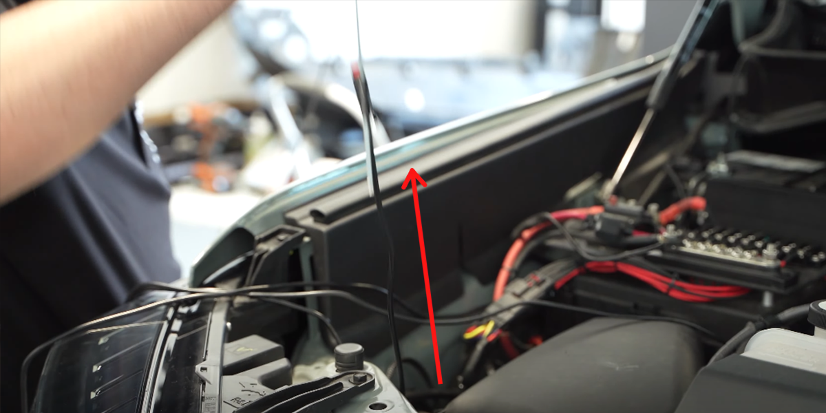
Tape the 5M M8 Extension to the steel fish tape and feed it up to the engine bay staying away from any hot or moving parts.

Route the 5M M8 Extension across the engine bay to the battery securing any excess wiring using zip ties.

Step 10 - Connect 3M M8 Extension (Left Front Wheel Well to Front)
Connect the 3M M8 Extension to the front-mounted Rock Light.

Route the wiring up behind the fender liner and down towards the front of the vehicle.

Re-install the plastic clips and bolt that hold the fender liner in place and zip tie any loose wiring.

Step 11 - Connect M8 Splitters (Front)
Connect an M8 Splitter to the 3M Extension from the left front wheel well to the front Rock Light.

Connect another 3M Extension in line with the M8 Splitter attached to the front Rock Light.

Secure any loose wiring using zip ties above the skid plate.

Re-install the 13mm skid plate bolts removed earlier.
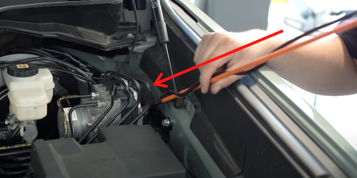
Step 12 - 3M M8 Extension Engine Bay Routing (Front)
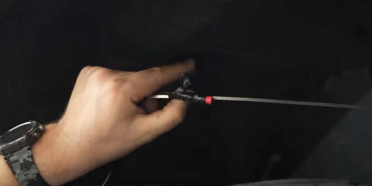
Feed a metal rod down the engine bay to our 3M M8 Extension.

Tape the 3M M8 Extension to the rod.

Feed it back to the engine bay to the battery away from any hot or moving parts.

Step 13 - 3M M8 Extension Engine Bay Routing (Right Middle)
Route the 3M M8 Extension from under the vehicle up to the engine bay near the battery using steel fish tape.

Step 14 - 1M M8 Extension Engine Bay Routing (Front Right)
Feed steel fish tape down the engine bay to the passenger front wheel well to our 1M M8 Extension.
Connect the 1M Extension to the passenger wheel well Rock Light.

Secure our extension wire to the steel fish tape to route up and behind the fender liner.
Feed the steel fish tape with extension wire through the engine bay near the battery.
Replace the plastic clips and bolts that hold the fender liner in place and secure any loose wiring.

Step 15 - Connecting M8 Wiring Harness
Connect the positive and negative leads include with the harness to the battery.
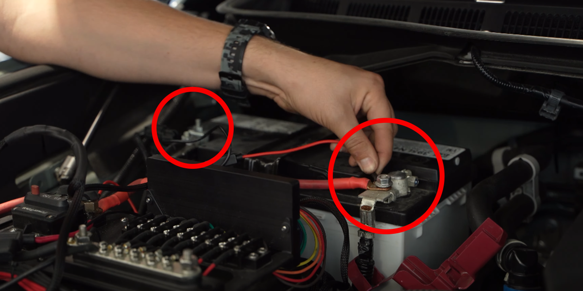
Connect the lead from the Bluetooth controller to the harness.
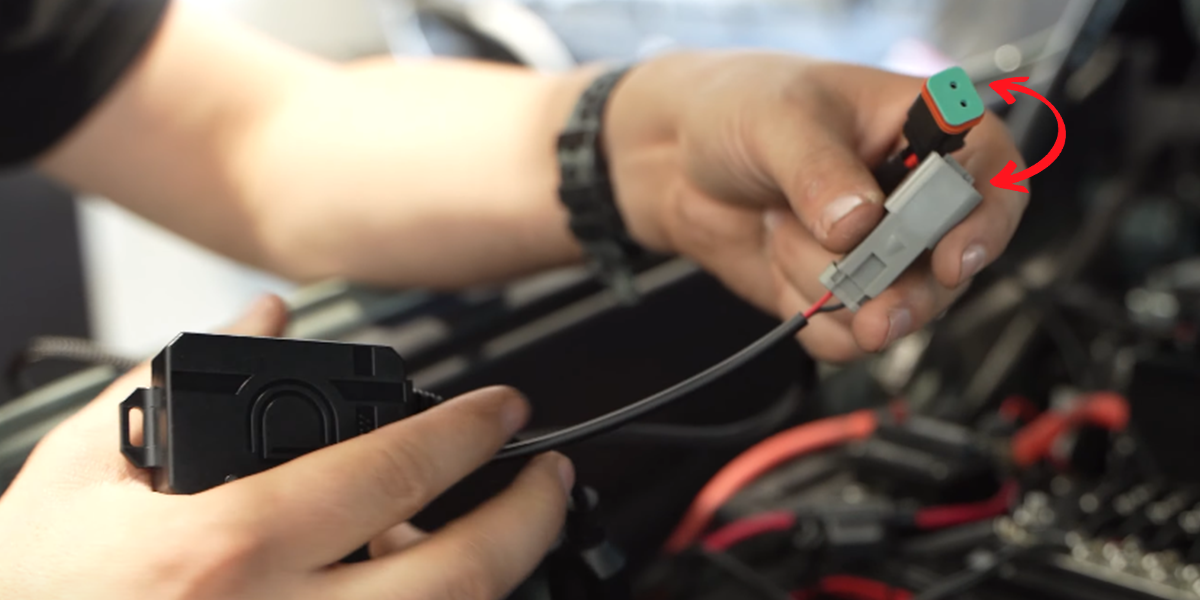
Plug the M8 connectors from our Rock Light leads into the M8 connectors on the included harness.
![]()
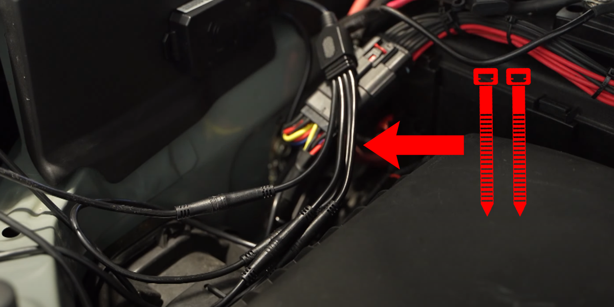
Zip-tie any loose wiring away from any hot or moving parts.
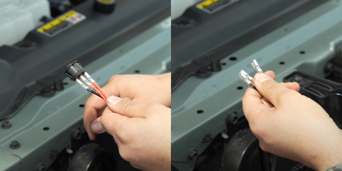
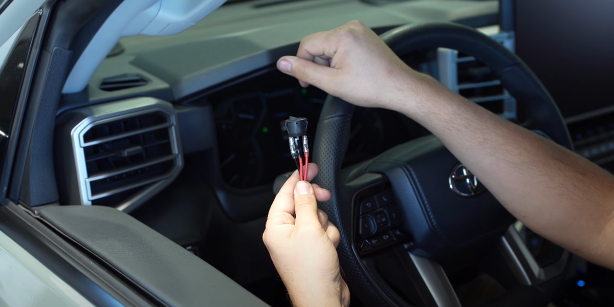
Step 14 - Route Toggle Switch
Remove the toggle switch from the wire harness.
Tape the wire leads from the harness to a metal rod.
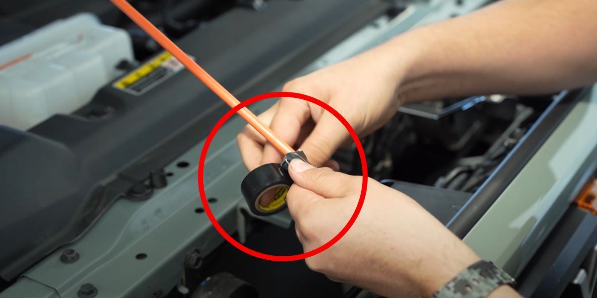
Fish the rod through the engine bay away from any hot or moving parts and through the firewall into the cab.
Re-connect the switch to the wire harness and install it in the cab at the location of your choice.
The installation is now complete. Enjoy your Stage Series Rock Lights!
Questions About the Installation?
If you have any questions or issues installing the Stage Series Rock Light Kit, please contact us for further assistance.
Where Can I Buy Stage Series Rock Lights?
If you're ready to upgrade your vehicle with Stage Series Rock Lights, click here or use our dealer locator to find a dealer near you.
Want to know more about Diode Dynamics products? Visit DiodeDynamics.com and subscribe to our newsletter for new product releases and more!
This Installation Guide is for the following SKUs: DD7743, DD7742, DD7744, DD7744C, DD7745, DD7745C
Share This Post